3. Computer controlled cutting
All the safety instruction and how to use the laser is documented as a group work here: Link to group work
The introduction given by Gleb was really helpful. When I started to laser my model, I was able to just look up our documentation on how to set up the laser. It's super easy to remember how to operate the laser.
This also includes calibration tests for the most important laser parameters.
Construction kit: Moose head
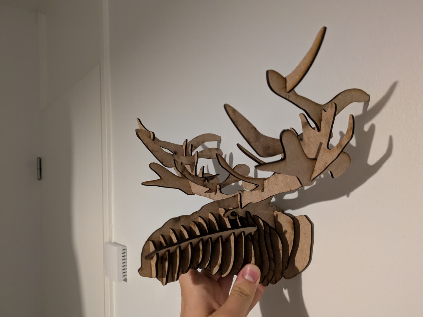
Since I wanted to create a more artistic model for the lasercutting part I decided to model it using a software called Flatfab. It makes modelling laser cuttable kits easy. As we will see, using the finished model and cutting it eventually was more difficult. This definately resolved some of the advantages, leaving it still a good choice for artistic models.
Creating the model
I installed Flatfab and started it. It was not really intuitive so I started to watch the tutorials they provide on their youtube channel.
Opening a new flatfab file shows you the most important control keys:
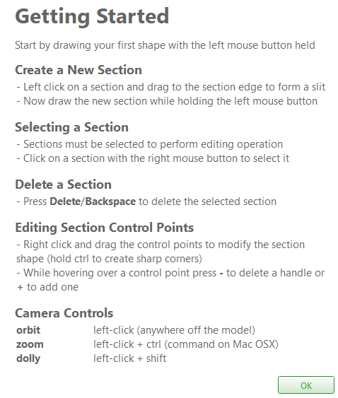
I searched for the option to create more control points on a spline way too long just because I didn't read the Getting started window.
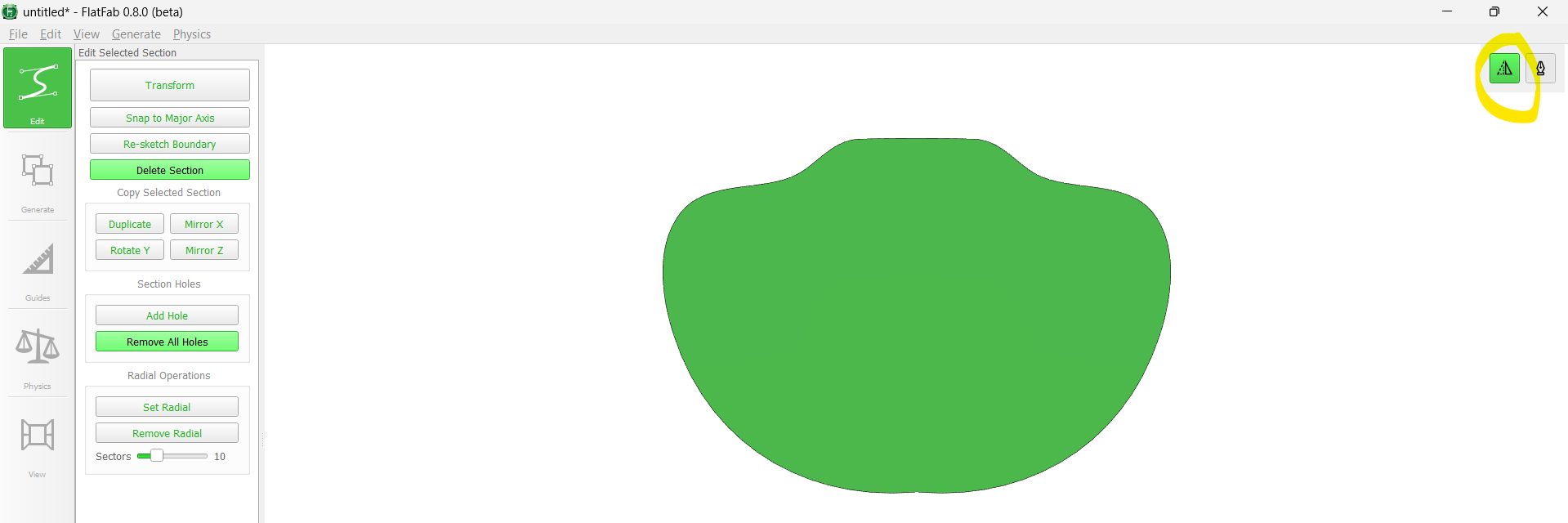
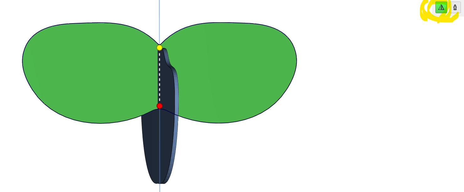
You can create a symmetric main body by enabling this button:
If we want to create a connecting piece we will first draw a straight line on a existing tile. The software will aumatically mark the start of the generated slot with a red and the end of the slot with a yellow point. You will always start to draw the slot from the middle of the tile to the edge.
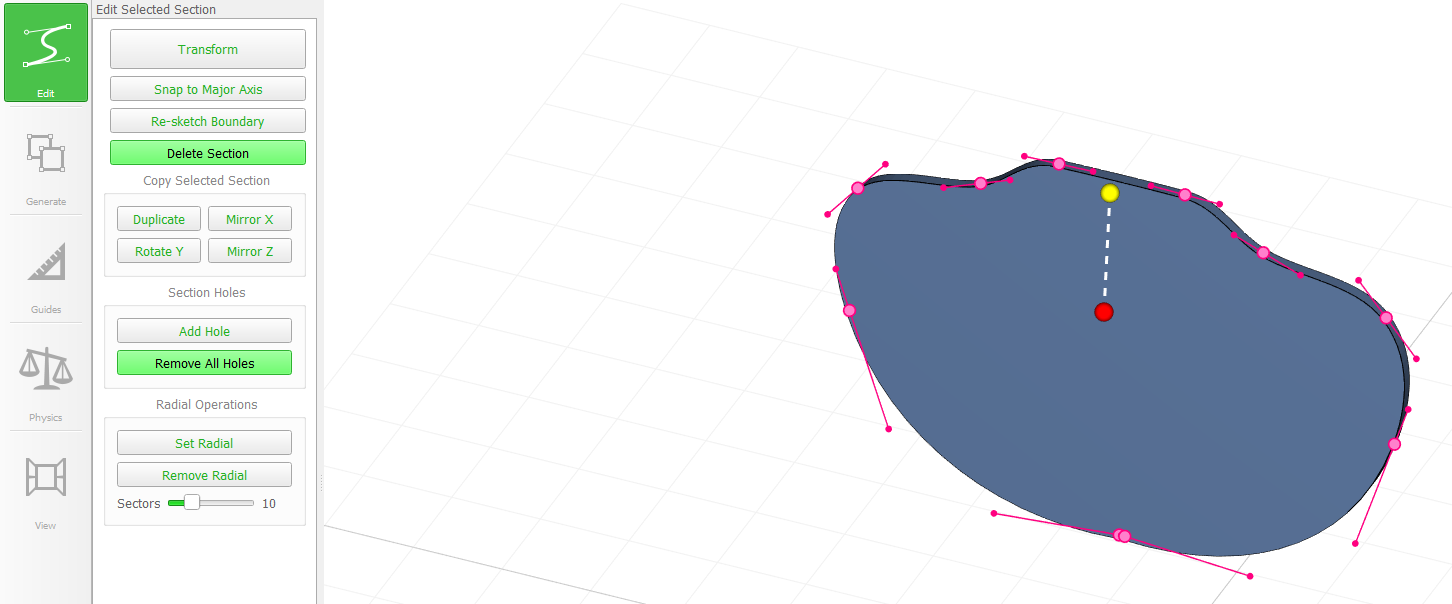
Exiting the edge, will show you the "drawing mode" for the new tile. There is a deadzone where you can move your mouse without already drawing the new tile.
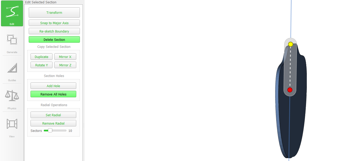
You will start drawing the boarder of the new tile. Here you can enable the symmetry function again, if you like.
Drawing without a symmetry function can result in a new tile looking like this.
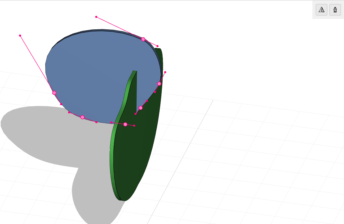
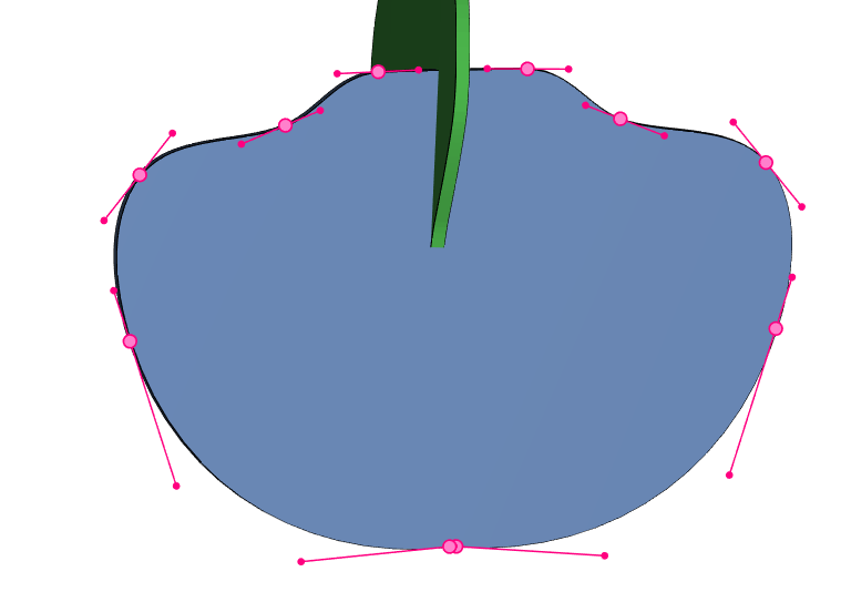
No newly drawn tile is perfect so you can adjust the outer tile line by moving around the control points. You can add or remove points in spline sections like in inkscape.
For the moose head I used a reference picture to draw a well looking base tile. For that I looked for a 2D image of a moose head.

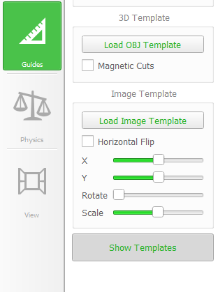
I loaded it into the software using the according function. You can scale, rotate and move the image into x and y direction on the plane it lies on:
I used it do draw the rough outline and went completed to outline moving and adding control points:
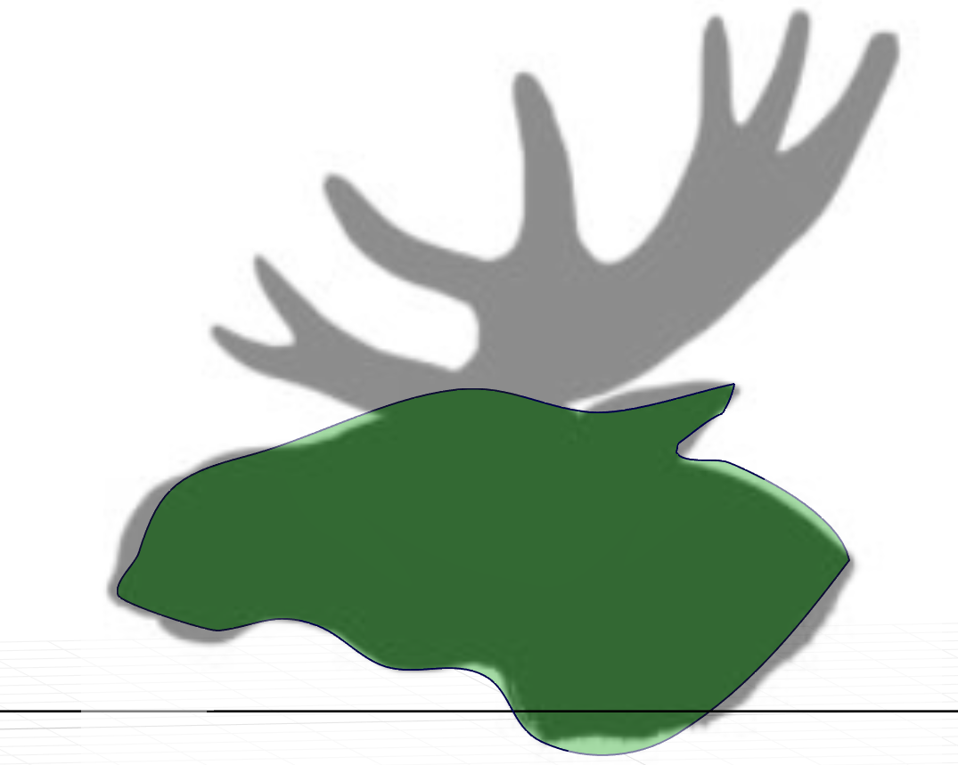
I came up with this final tile.
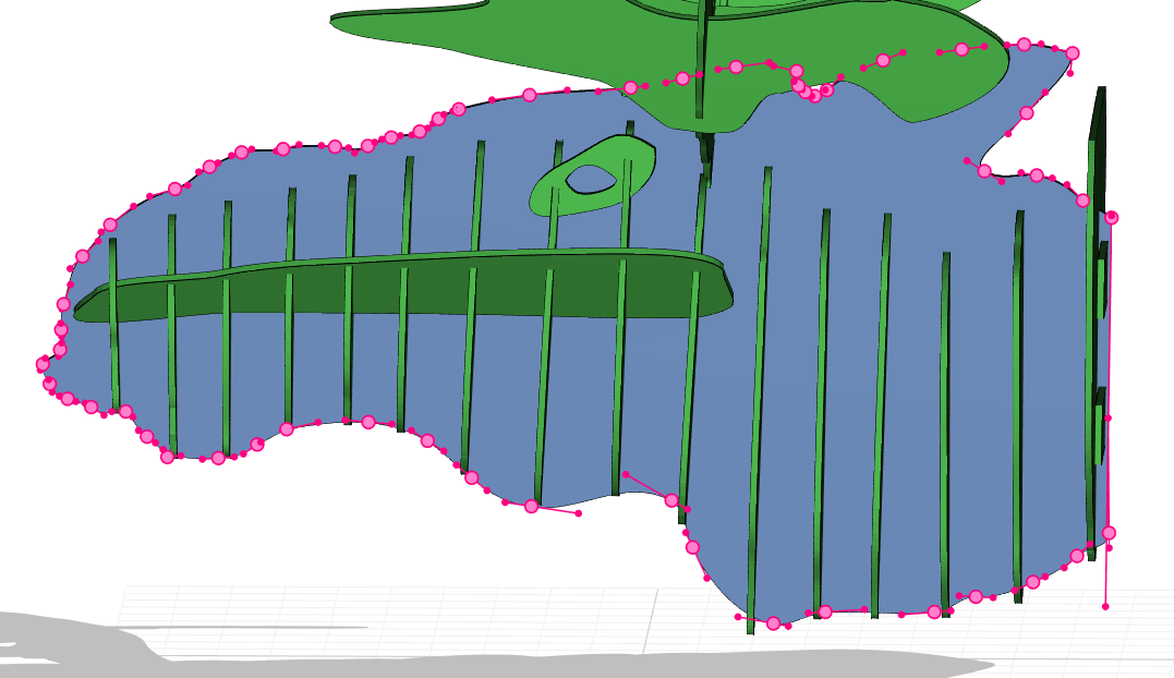
From then I went on, creating the tiles of the outer elchs head using symmetry each time:
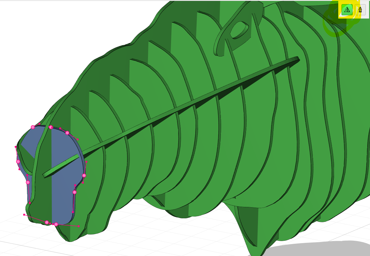
It's also possible to create tiles with two slots. The software will generate the second one, when the newly drawn tile colliides with further already existing tiles.
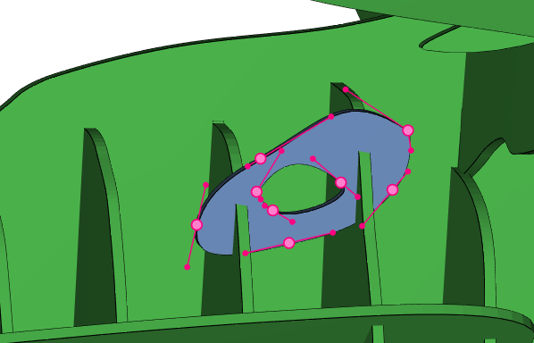
I used the mirror x/y function to mirror parts, that occur on the other side of the moose head as well (for the eyes and antlers).
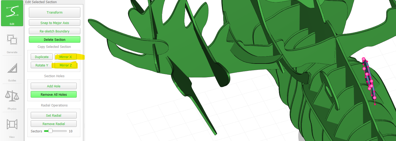
Thats every function I used to come up with the model of the moose head. I was told about slicer for fusion afterwards and discovered it just a bit.
It has an option to convert a .obj file into a modelling kit: Importing a moose head 3D model I find on the internet:
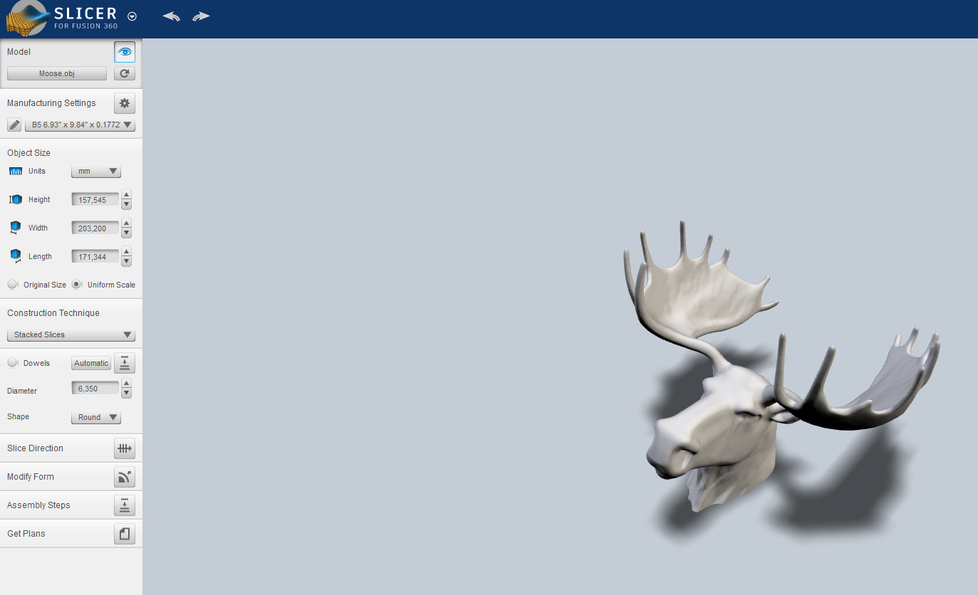
This can be converted into a laser cuttable design automatically.
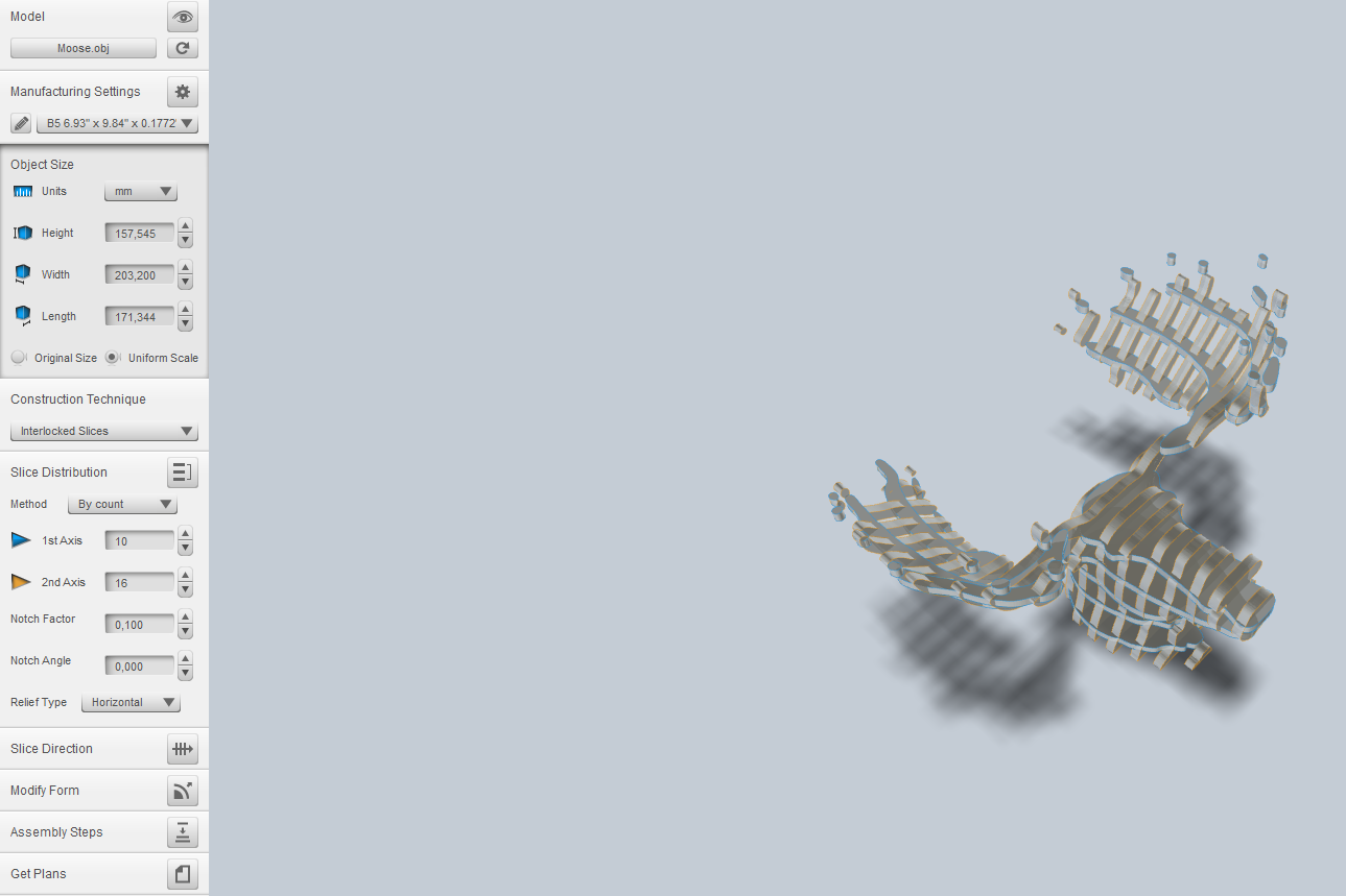
Since I didn't have a suitable 3D model of the moose head I am happy I did my design in FlatFab.
Manufacturing fun with the model:
I used the Epilog Fusion 75 W CO2 Laser to manufacture the part.
Doing the modelling was quite fun using the software but manufacturing was not easy.
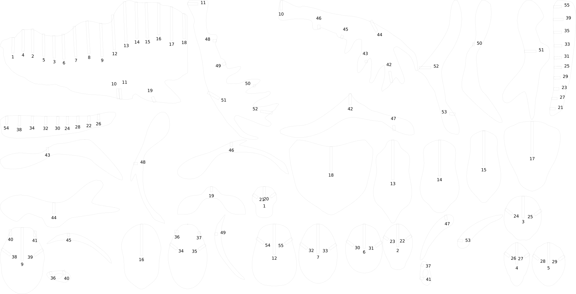
The first problem occured when I first exported the SVG file from the program:
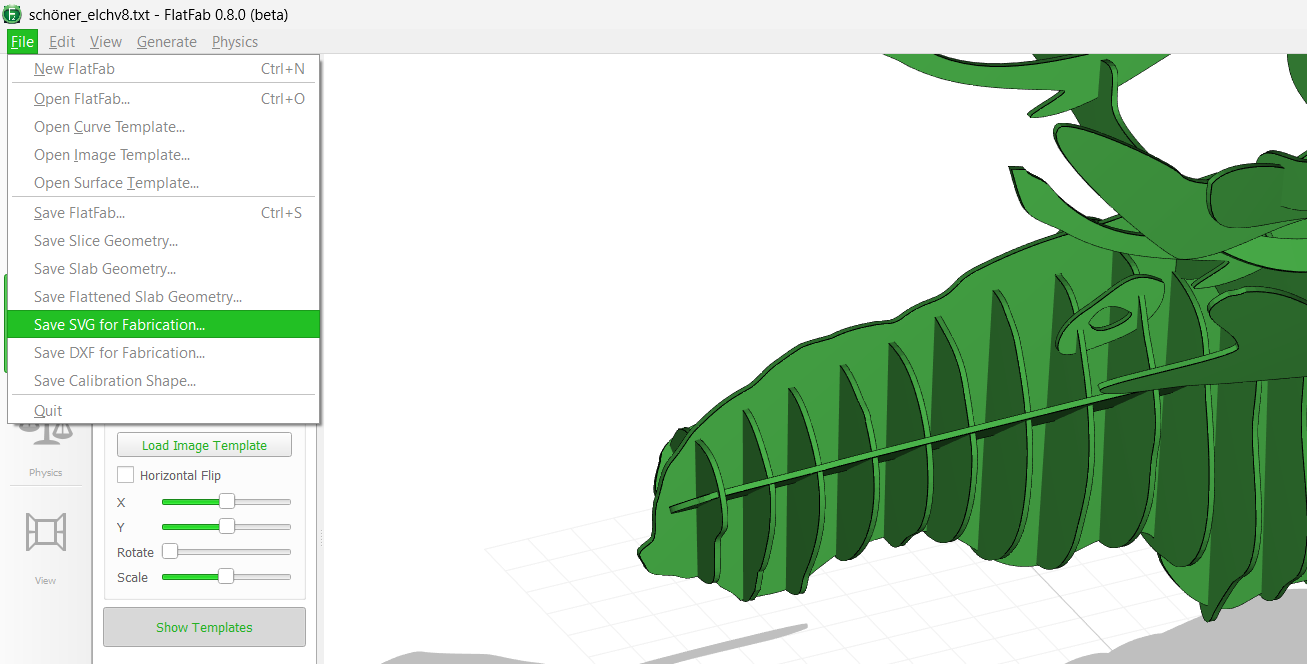
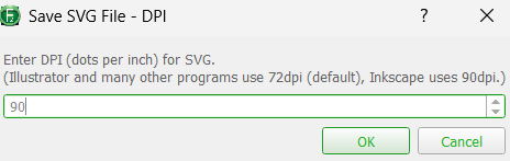
This was the SVG file.
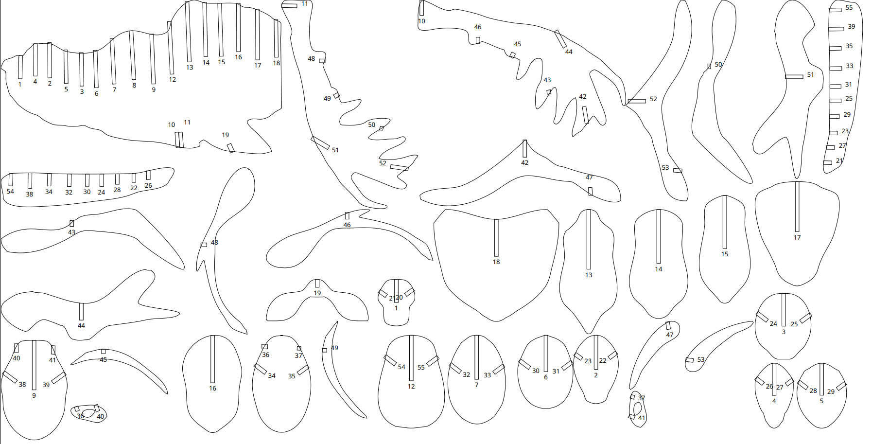
Having a close look I could spot something that would become an issue later on. Some slots were not properly generated.
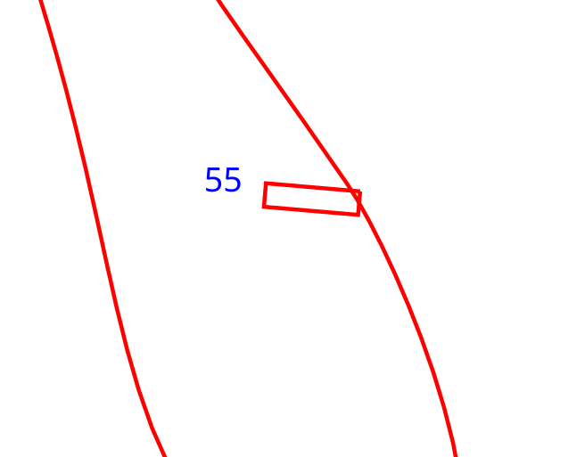
So I used inkscape to pull each rectangle closer to the edge.
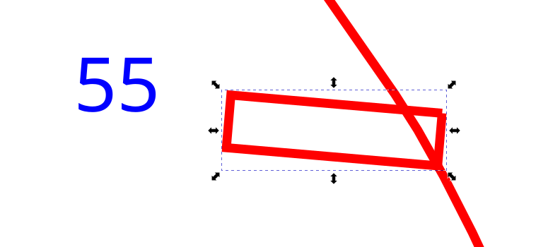
After fixing all slots with problems I went on to calibrate the slot width to have a proper press fit. To control this, flatfab had rather disappointing features not allowing to input a kerf value but to set a "Calibration" slider from 0 to 100%.
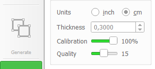
This decreases the slot width. For me only 100% was well fitting and reducing this value only made the slot too narrow. My material had a thickness of 2,6 mm. I went along testing slight differences in material thickness. For that I created a test part:
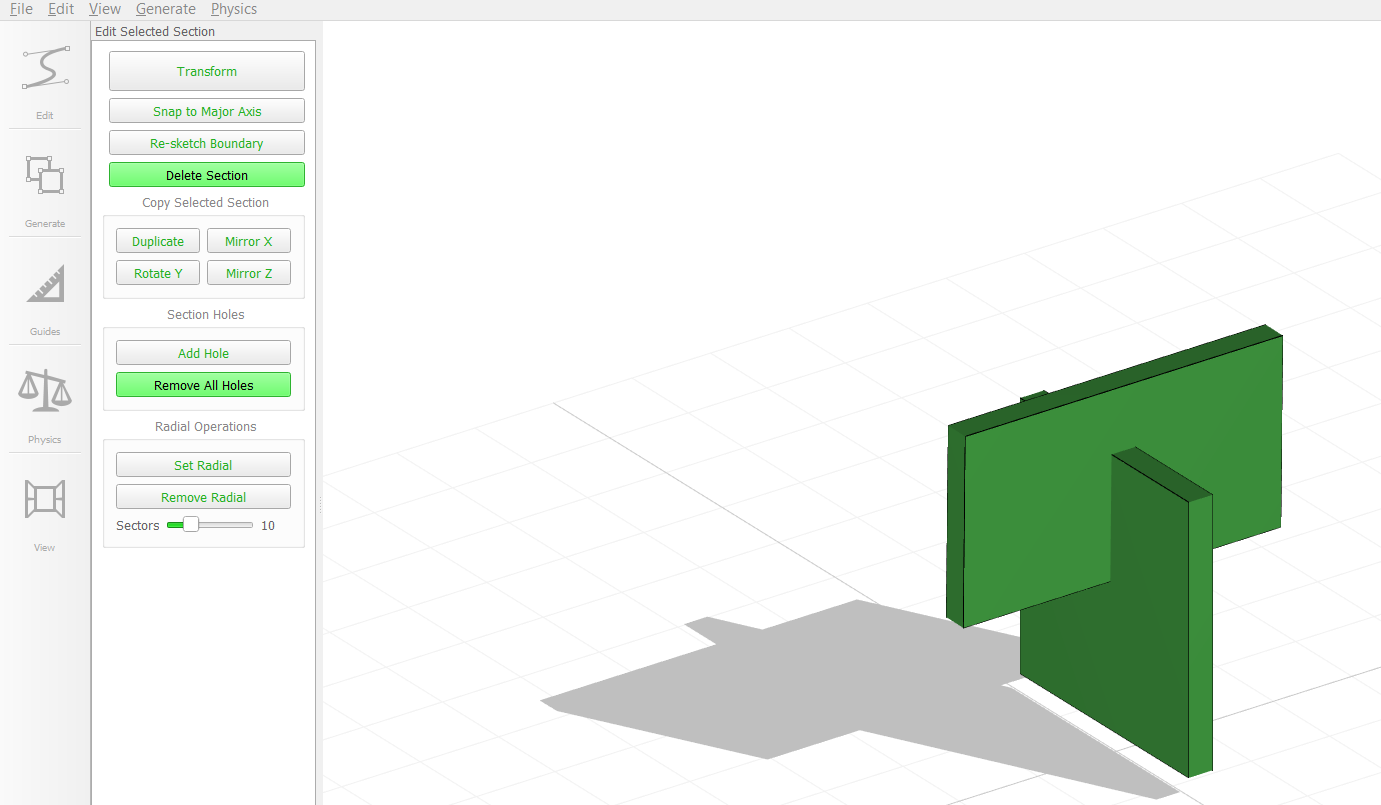
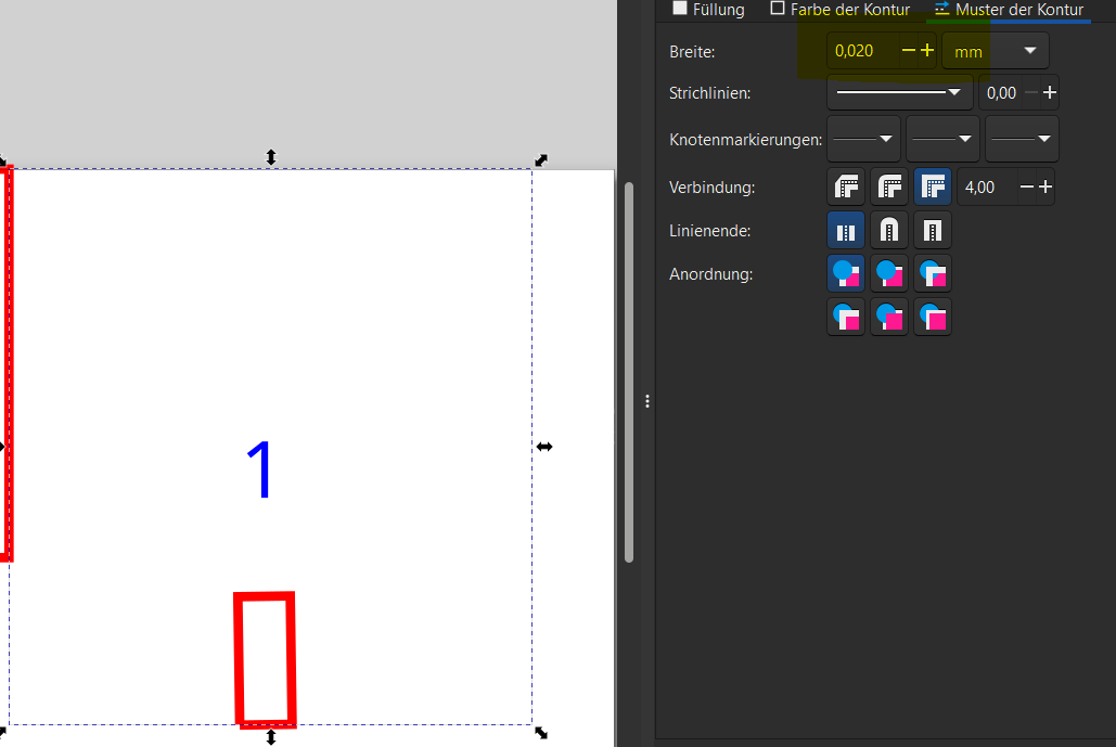
As for every svg i exported from flatfab I set the colour of cutting lines to black and the line width to 0,01mm using Inkscape. Engraving lines need to be wider than 0,02mm and need to have a filling.
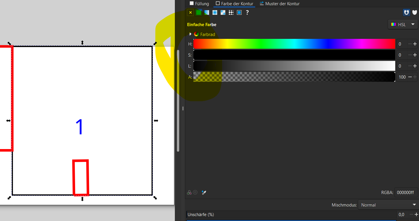
Thickness settings:
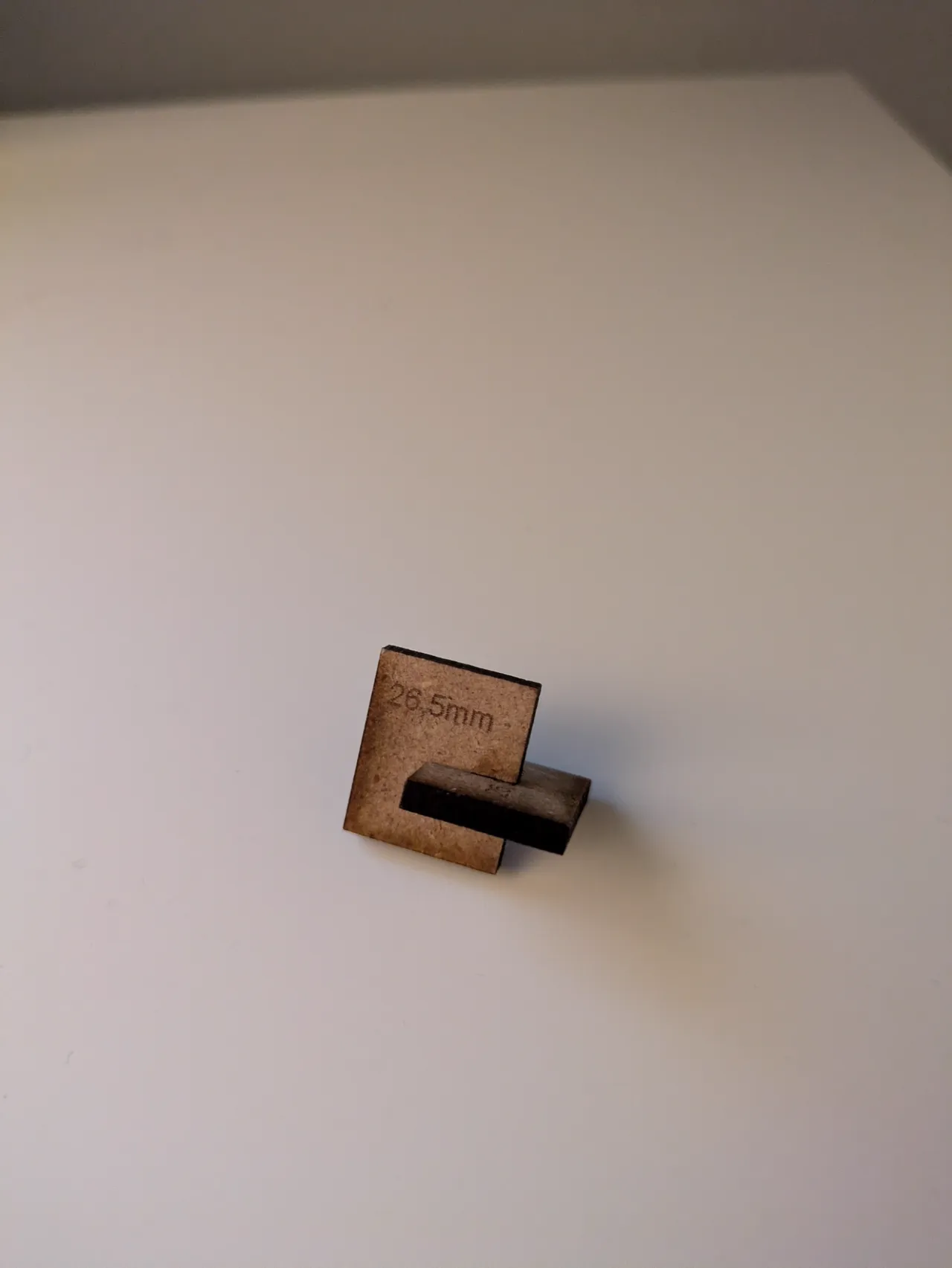
I generated multiple svg files with varying material thickness. I copied them altogether in a single inkscape file and added text that should be engraved and show the material thickness. I tried values from 2,55 to 2,7mm. 2,65mm showed the best press fit (wrong engraving):
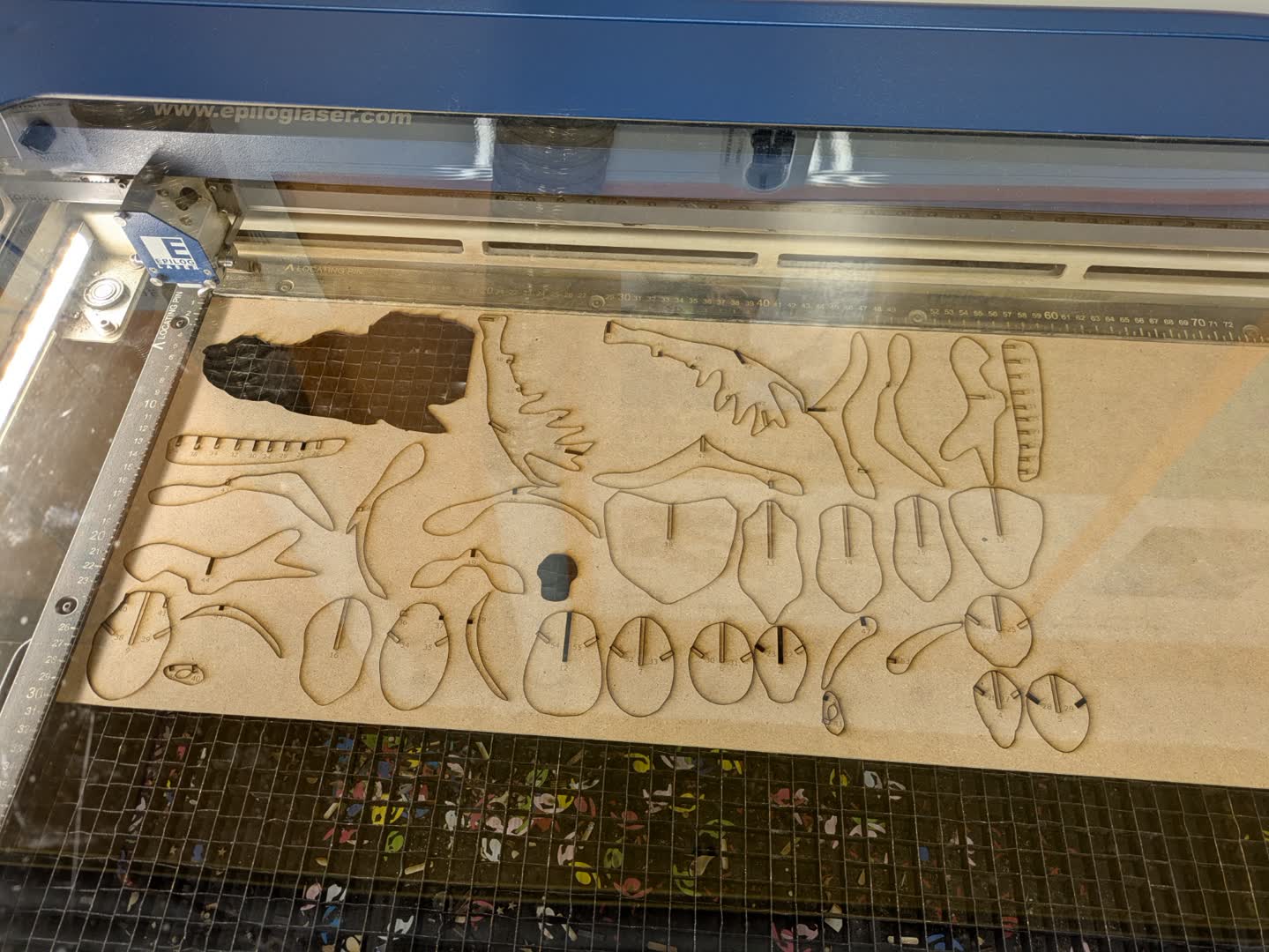
With that information I created the svg again with 2,65mm material thickness (although the material was 2,6mm) and lasered all the parts of the moose head:
The assembly went well overall. I had the problem that some single slots were too narrow or loose. That must have been slots that I corrected manually and changed the size mistakenly. For that reason I had to relaser 2 or 3 parts with corrected slot width using inkscape again.
Flatfab conclusion
As a conclusion I would say that using FlatFab is only worth it if you plan to design really artistic models. The design process itself works really flawless but exporting and manufacturing without the possibility to set required laser values makes it hard to deal with. It also doesnt allow exact dimension.
There is the function to set a dimension to a line that you draw on a tile.
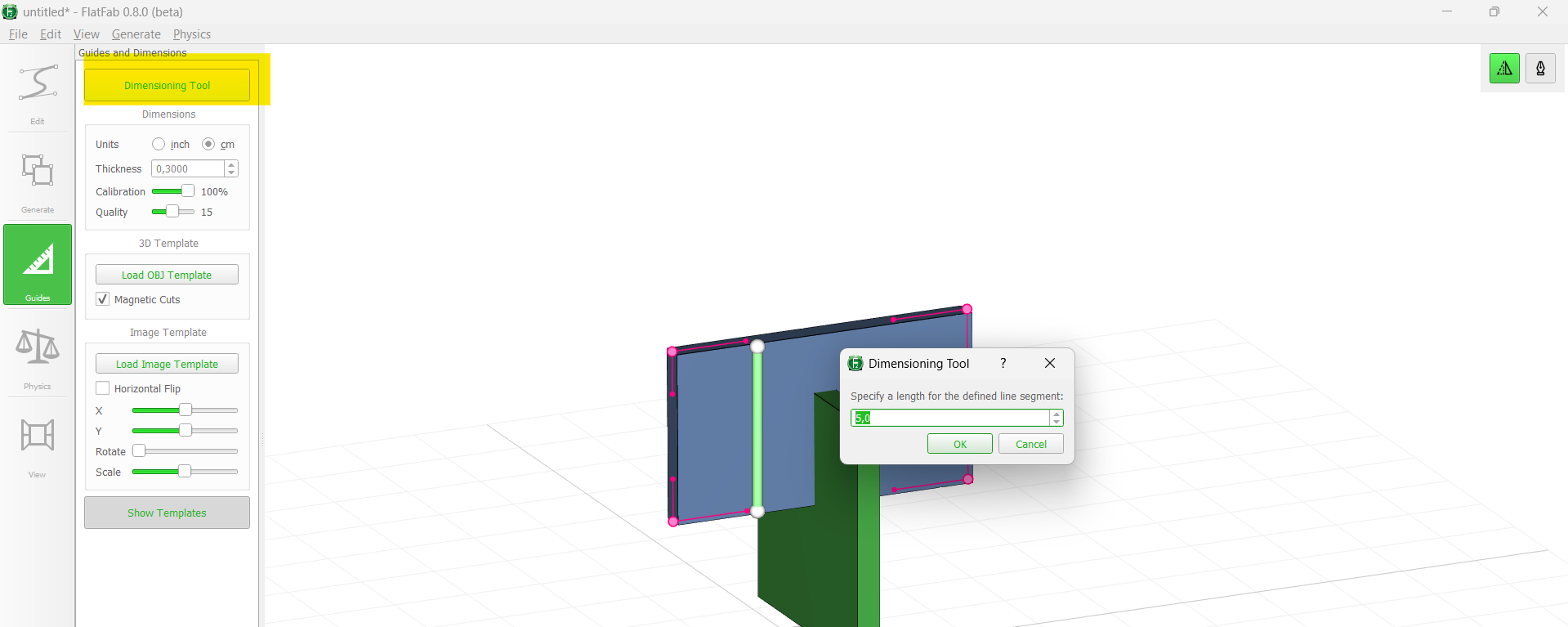
But that is not really exact and only allow incfluence on the rough model size.
Parametric modelling with Fusion360:
Fusion 360 allows to model parametric models suited for lasercutting.
Starting with a standart rectangle with a slot:
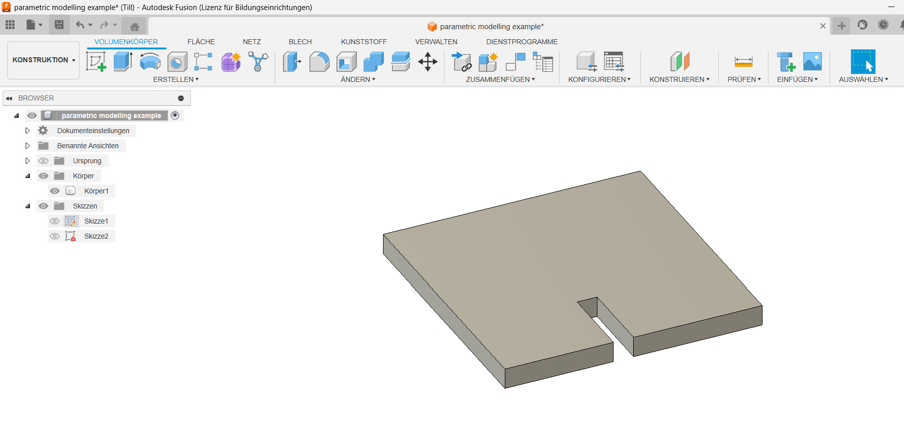
Instead of using numeric values for the slot with, it is possible to use a variable.
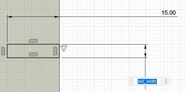
These can later be controlled in the "Parameters" menu:
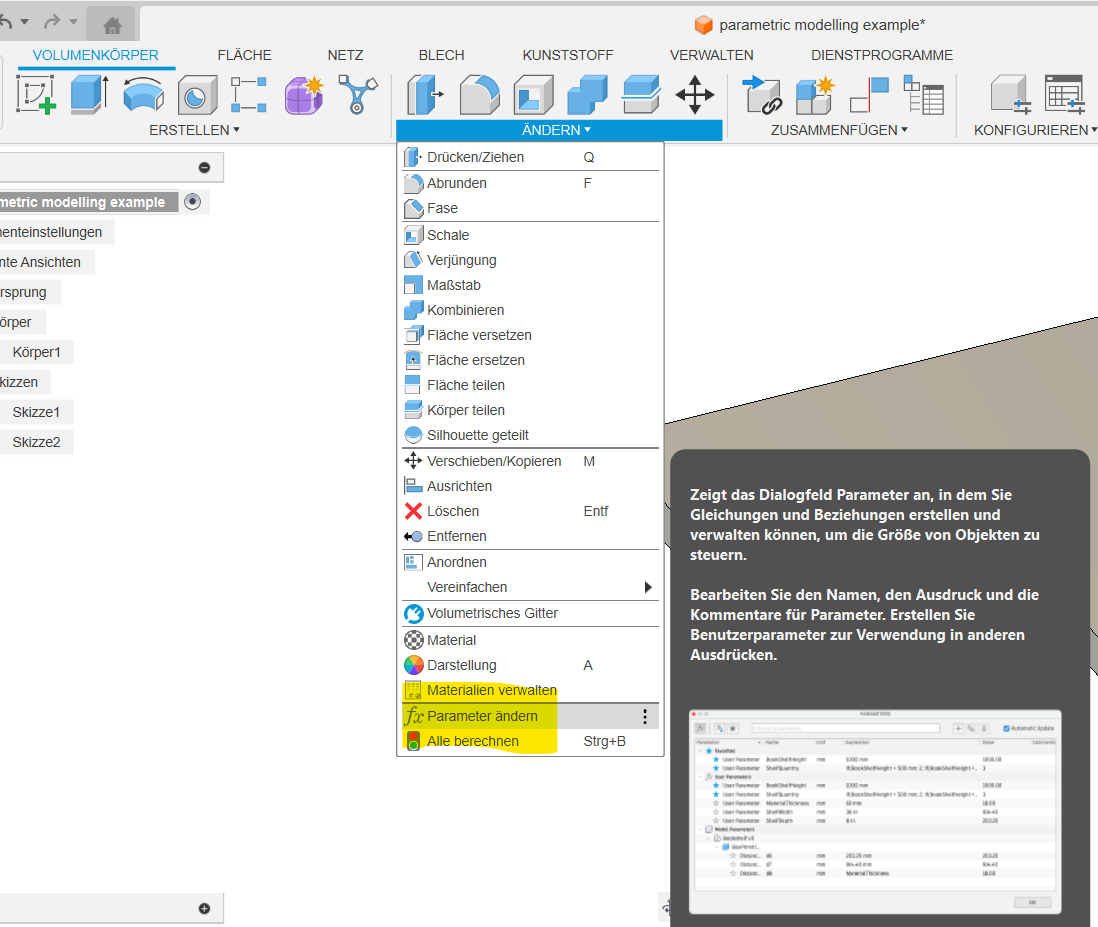
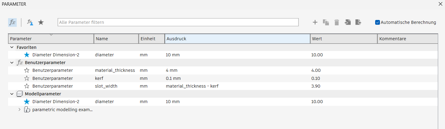
This allows to adjust the model after measuring the kerf.
Using the vinyl cutter to create reflectors
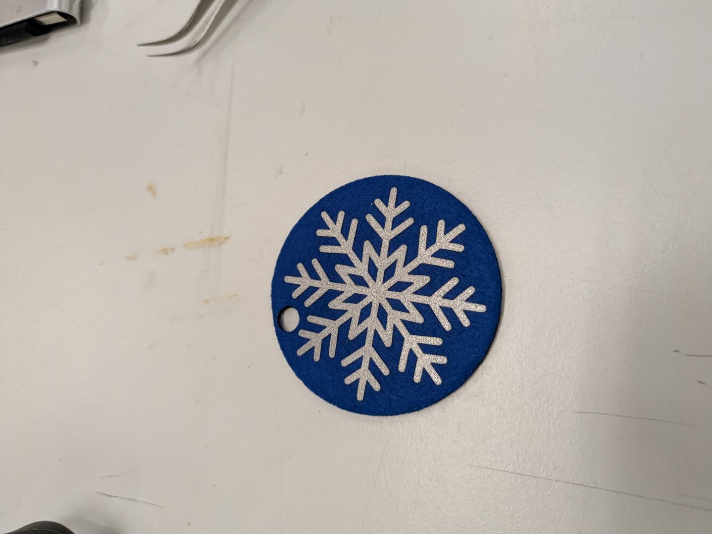
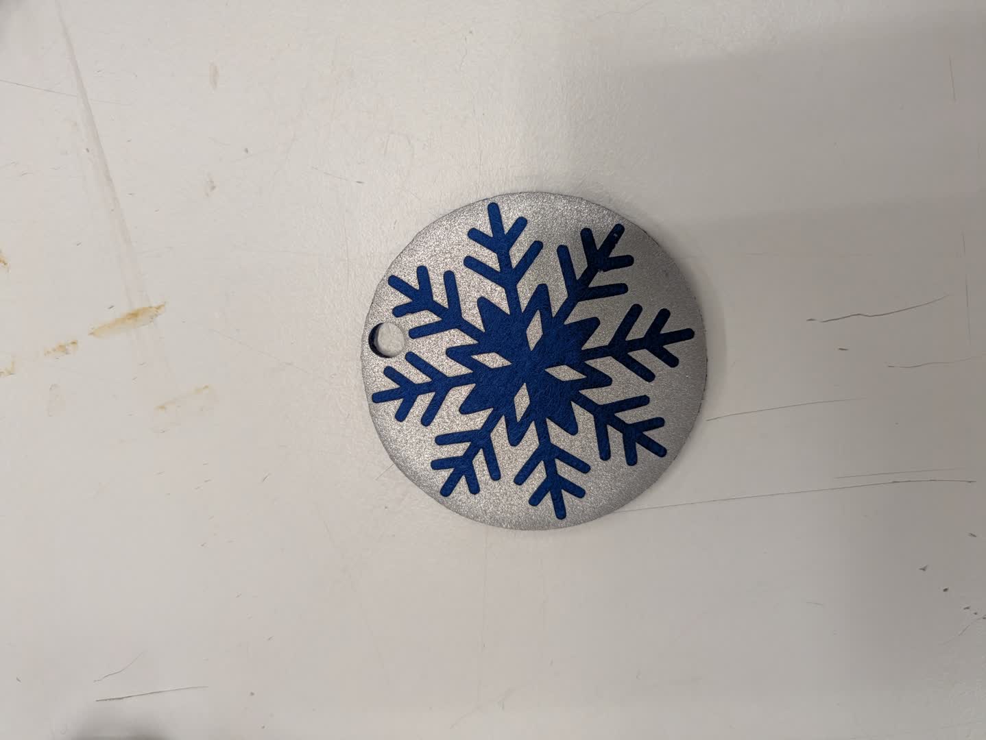
For my work with the vinyl cutter I chose to make some reflectors.
It is easily customizable and from what i've learned also common in Finland to hang them onto backpacks or clothes during the dark winter.
Creating the .svg in Inkscape
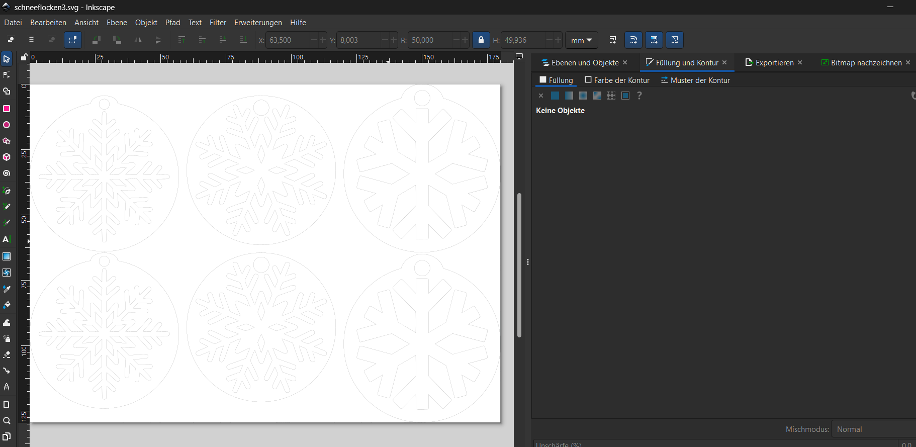
I created the .svg for the laser cutter in Inkscape using (once again) a raster image and the trace bitmap function to create a nice looking vector graphic.
Since I wanted the reflectors to be round I decided on a snowflake design (3 different) and also created the outer contour for the felt to be lasercut.
Using the vinyl cutter
Putting the vinyl in the machine
Before starting a cutting job from the pc the piece of vinyl that should be cut has to be arranged properly. The origin in vinyl cutting is bottom left and the design should be placed at the bottom left of the page.
Materials to use for vinyl cutting:
- Adhesive vinyl (e.g. for stickers)
- Non adhesive vinyl
- Paper
- thin metal foil
Possibilities regarding the material size
- Using a roll of vinyl.
- using a larger piece of vinyl
- using a small piece of vinyl taped onto a sheet of paper/carton
In my case I had a small scrap piece of the reflective vinyl so I taped it onto a carton. For adhesive vinyl it's important to take care the right site is facing up!
When placing the material into the machine it is important that it covers the material sensor. It uses it to find the edge of the vinyl:
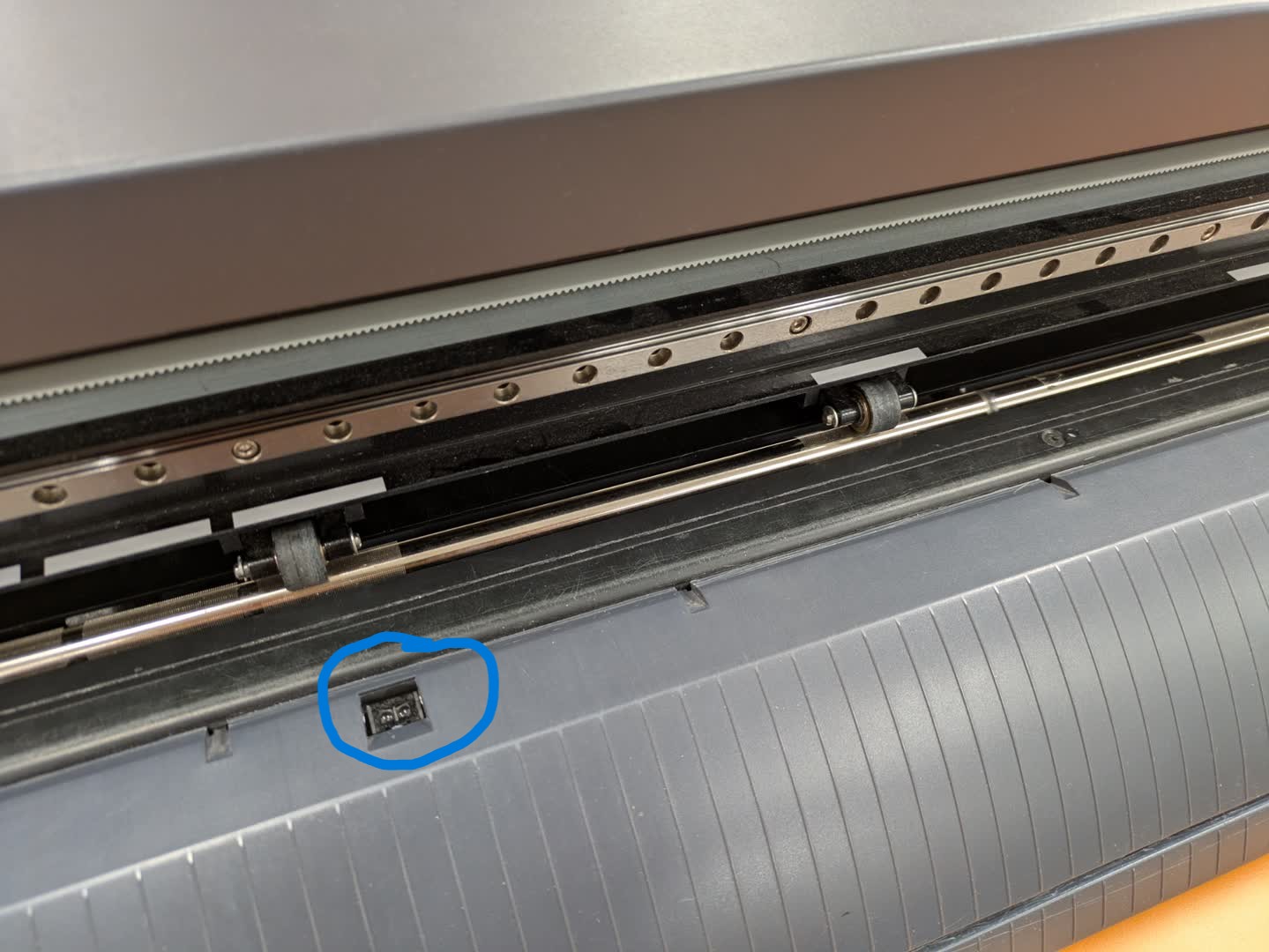
The vinyl also has to be aligned as straight as possible so that the wheels stay on the vinyl all the time pushing it back and forth.The vinyl is fixed using this lever:
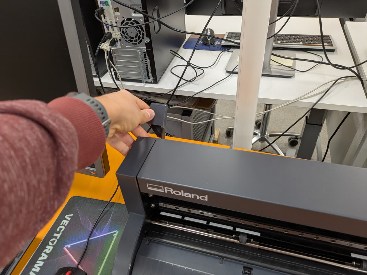
The wheels position can be changed by moving them left and right. IMPORTANT: The wheels always have to be in the marked sections for the machine to work. Otherwise it won't start operating.
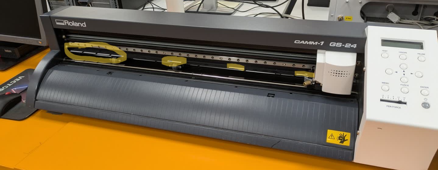
When using a really thick or hard material it can be necessary to adjust the cutting force.
Finally we let the cutter find the edge of the material.
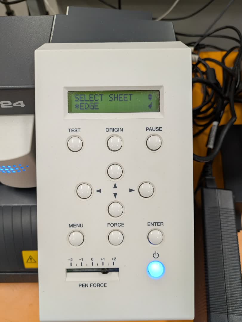
We adjust the machine head to the position where the origin should be and set the origin by holding the "origin" button until it says that the new origin is set.
Starting the cutting job on the pc
After putting the vinyl in the machine the cutting job can be setup.
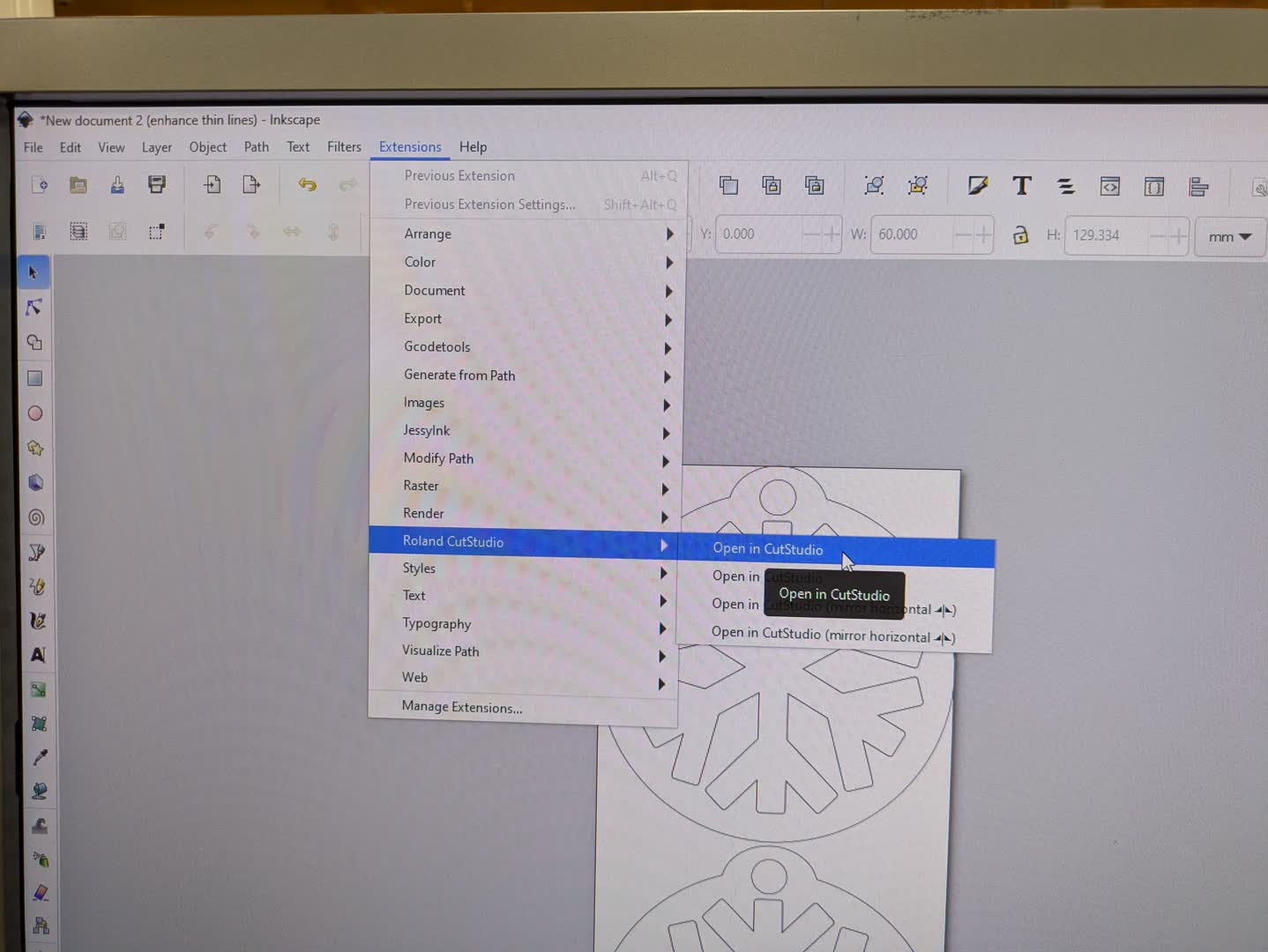
We do so by opening the Inkscape file on the pc. We will use the Roland CutStudio extension in inkscape:
Roland Studio will open and we can once again control the dimensions of the cut. It also allows small design changes but usually it's easier to do that in inkscape.
We send the cut to the machine by clicking on cutting and confirming.
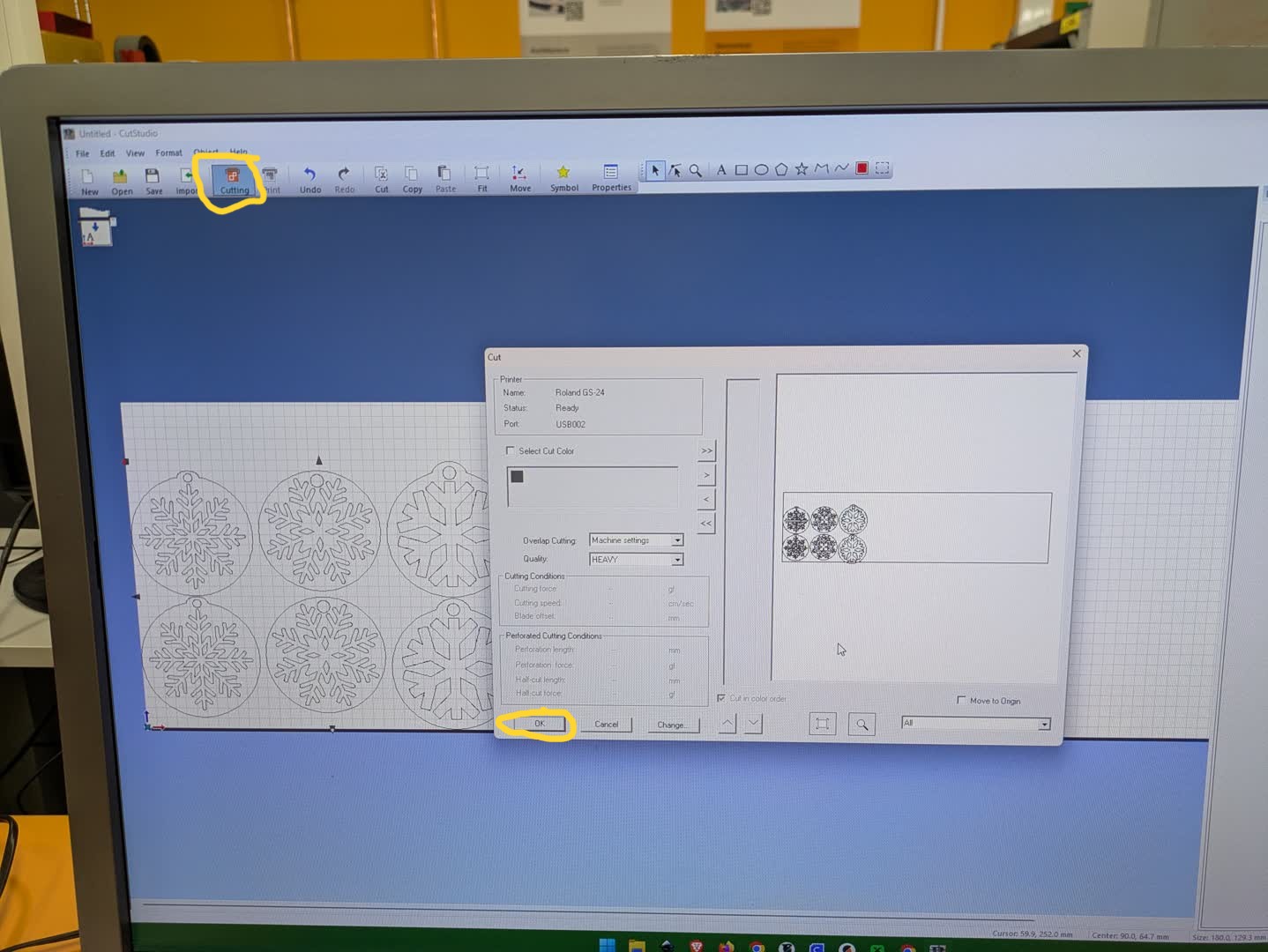
The machine will then start cutting:
After the job is done, the toolhead will move to the side. After that we can loosen the vinyl and take the cut vinyl out of the machine.
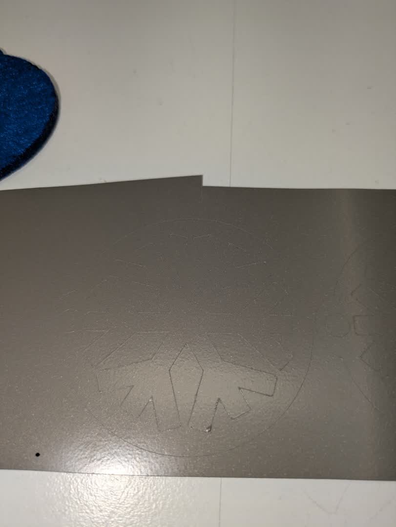
It is good to check if the machine cut throught the vinyl:
Lasering and assembly
Afterwards I used the laser cutter for the felt base of the reflectors:
With the felt pieces and the cut vinyl I could go on with the assembly and pressing of the reflectors.
I peeled the snowflakes of the vinyl using tweezers and arranged them onto the felt pieces:
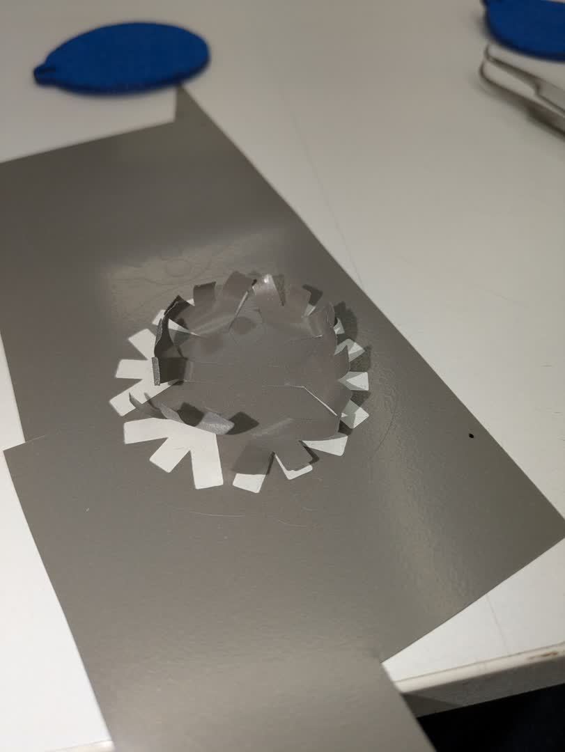
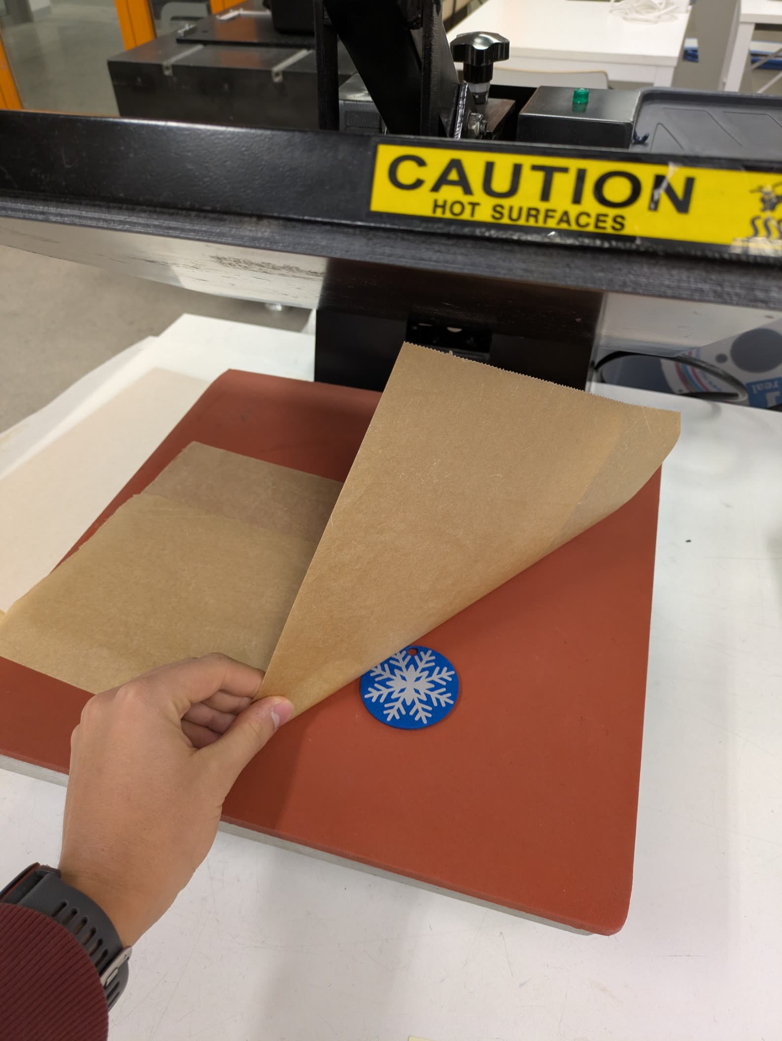
I used the heatpress to melt the glue on the vinyl making it stick to the felt. The temperature was 145°C and duration 12s.
Used files
| File | Format | Download |
|---|---|---|
| final flatfab file of the moose head | .txt |
Download flatfab file |
| moose head 3d model | .obj |
Download moose head 3D model |
| laser cut file | .svg |
Download svg for laser cutting |
| stl file of model | .stl |
Download model |
| snowflake reflectors | .svg |
Download svg to edit in inkscape |
| laser cut file snowflake reflectors | .pdf |
Download pdf for laser cutting |
| vinyl cut file snowflake reflectors | .pdf |
Download pdf for vinyl cutting |